About Project
Technical
Approach and Understanding
The
whisker-inspired flow
sensors will be constructed using the magnetostrictive Galfenol wire
developed
at the University of Maryland. One end of a Galfenol whisker is fixed
and the
other end is free to deflect under fluid flow-induced drag forces as
seen in the
figure below. The bending-induced stress near the fixed end of the
whisker
produces local changes the magnetic domain orientation, which is
accompanied by
a global change in the magnetic flux density in the whisker,
demonstrated in the figure
below. A giant magnetoresistance (GMR) sensor at the fixed end of
whisker is
used to detect this change of magnetic field and to convert it into
an electrical
signal that, once amplified, can be easily transmitted as needed. A
permanent
magnet must be placed in contact with the whisker to align magnetic
domains
along the whisker when it is not deformed. Different strength magnetics
can be
used at different locations, as long as a proper magnetic field
strength is
achieved at the root of the whisker to ensure internal magnetic dipole
rotation
in response to bending of the whisker without saturating the GMR
sensor. The
sensor configuration is very simple to assemble from five main
components: the
whisker, a GMR sensor, a clamping fixture, a small permanent magnet and
a small
low power operational amplifier.
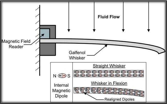 |
Theory behind magnetostrictive flow sensor
Application
to bridge piers
The
objective of this project is
to test and deploy an embedded array of sensors located on or near the
outer
surface of the bridge foundations, at varying heights, that can
determine the
sediment depth and profile around the foundation in real time. The
sensor array
will be composed of bio-inspired, whisker-shaped magnetostrictive flow
sensors
that are highly rugged and detect water flow by bending, see the
figures below.
Those sensors located above the sediment level will be free to move
with the
current flow and will yield dynamic flow measurements. Those sensors
located
below the sediment line will be trapped and will return only static
measurements. Knowledge of sensor depth will help to determine the
sediment level
in real time. An automated data acquisition base station will monitor
sensor
signals from above the water line, differentiating between static and
dynamic
sensor readings, estimating the sediment and water line elevations,
monitoring
for sensor failure, and sending scour alerts to relevant authorities to
be
visualized using the decision support engine.
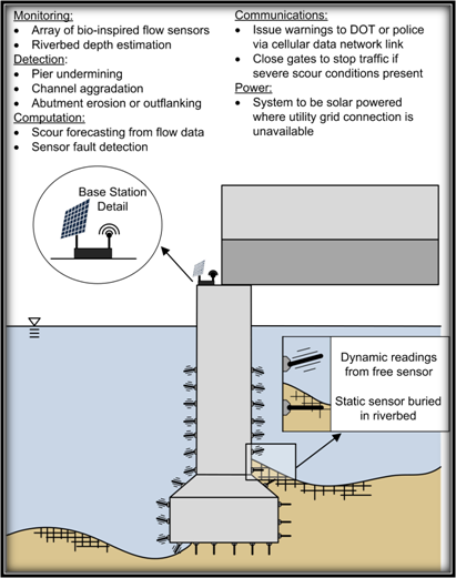 |
| (a) Overview of bio-inspired scour sensor array concept for bridge piers |
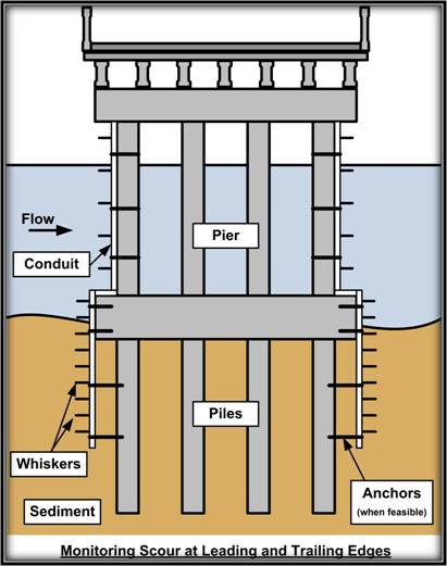 |
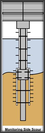 |
| (b) Installation concept for monitoring the leading and trailing edges | (c) monitoring side scour |
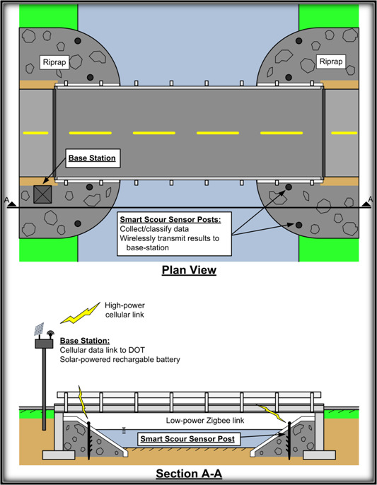
Wireless
smart scour-sensing posts for abutment, culvert, and bank monitoring
To
make installation of scour
sensor elements as practical as possible, modular sensor units, known
as “smart
scour-sensing posts” will be used in this project. These modular units
shown in the
figure on the
left below consist of several magnetostrictive transducer elements,
embedded
data collection and interrogation electronics, a wireless communication
interface, and a long-lived battery pack packaged in a galvanized steel
post
that can be driven into the ground near abutments, culverts, and in
embankments. These devices are wireless to eliminate the need to run
signal
cables in the vicinity of the bridge. They will utilize low-power
wireless
signal networks (e.g., Zigbee) to
communicate with local base stations that will aggregate the data from
multiple
on-site posts and send it via cellular data link to remote users.
Low-power
components and use of sleep mode will be employed to extend the battery
life
with the aim of achieving a battery life of ten years. An illustration
of the
proposed installation approach for monitoring of a bridge abutment is
provided
in figure on the right.
 |
 |
| Smart scour-sensing post. | Installation of posts at bridge abutments. |
Culvert
monitoring:
Scour at culverts induced by exiting flow patterns can be detrimental
and
threatening to the culvert stability. Riprap placement at the outfall
can
retard scour but has been shown to also fail under high-flow
conditions. Scour
occurring below the culvert foundation can result in culvert collapse
and
subsequent bridge or road failure. To detect this scour, smart
scour-sensing
posts will be placed on the downstream side of the culverts as close to
the
mouth of the culvert as possible, shown in the figure below. A nearby
base
station will collect the data from any posts within range (up to 700 m)
and
transmit that data to remote managers.
Monitoring
of bank stability:
Riverbank erosion is prevalent in rivers in which a river is not in
equilibrium with its watershed due to watershed development or extreme
rainfall
events. Sensors will be located vertically in the riverbank at various
lateral
locations to detect loss of the embankment depicted below. The depth
and number
of these posts will be determined based on input from DOT agencies. A
nearby
base station will collect the data from any posts within range (up to
700 m)
and transmit that data to remote managers.
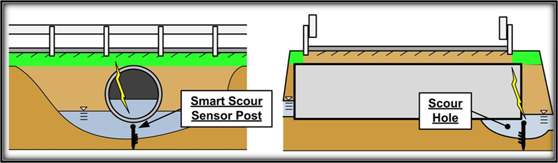
Monitoring
of
culverts.
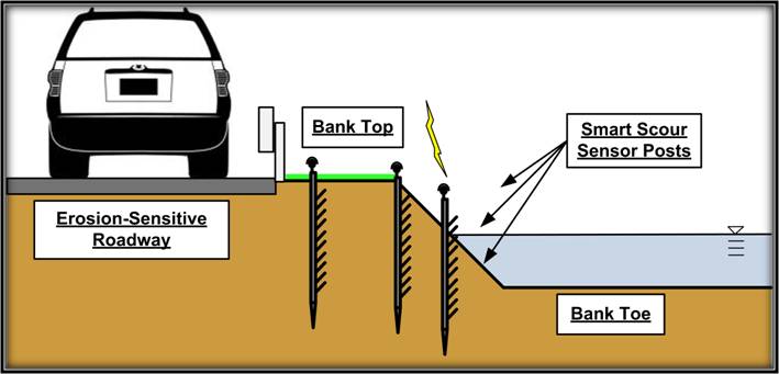
Monitoring of bank
stability/erosion.
Numerous technical
barriers are
anticipated and must be investigated during the course of the project.
This
section will discuss these barriers and the planned approach for
overcoming
them in four broad categories: 1) those barriers associated with sensor
protection; 2) those associated with signal generation; 3) those
associated
with signal processing and classification; and 4) those associated with
flow of
data/information and decision support. Each of these categories of
challenges
is discussed below.
Sensor
Protection:
Despite their inherent mechanical robustness, protection of the
proposed
magnetostrictive sensors from corrosion is an issue that must be
addressed for use
in their application. Galfenol is an iron-based alloy which has
corrosion properties that are similar to those of steel. The flow
sensor design
must incorporate sufficient corrosion protection for the Galfenol
whiskers to
have a life expectancy that is matched to the life expectancy of the
batteries
that power the wireless data acquisition system.
Tata Steel
(tatasteel.com) has a
comprehensive publication to provide "guidance on the corrosion and
protection
of H-section (steel) universal bearing piles.” They note that fresh
water can
contain dissolved salts, gases or pollutants that are harmful to
ferrous alloys
(like Galfenol). And although corrosion loss from river water immersion
is generally
lower than for seawater, their report shows results from studies of
H-section steel
bearing pile corrosion that exhibited corrosion rates in fresh water of
0.02 –
0.05mm/side/year, and in corrosive soils of up to 0.015mm/side/year.
With these
corrosion rates, if made from an unprotected Galfenol strip with a
thickness of
0.50 mm, the proposed whiskers would vanish several years (<5)
after
installation.
Canadian researchers
have
conducted the only known studies on the corrosion of Galfenol. Their
studies suggest
iron provides a good basis for initial Galfenol corrosion design
considerations.
They indicate a negligible corrosion rate for Galfenol (with gallium
content
that ranges from 15% to 27%) in de-aerated 3.5%NaCl solution at 25oC.
They suggest that this because a protective film is formed on the alloy
surface
causing its potential (E) to fall below -0.79~-0.86, which is below the
cathodic protection criterion for iron.
Compositions of Galfenol, AISI 1021 steel, and bearing steel.
| Sample | Ga | C | Mn | P | S | Cr | Si | Fe |
| Galfenol | 15-27% | balance | ||||||
| AISI 1021 steel | 0.18-0.23% | 0.60-0.90% | 0.04% | 0.05% | 1.00-2.00% | balance | ||
| Bearing steel | 0.55-0.78% | 0.10-1.15% | 0.05-2.00% | balance |
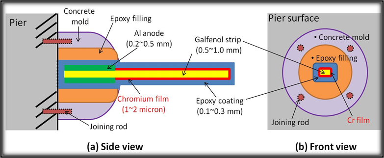
Schematic
diagram of corrosion-protective
layers for Galfenol strip mounted on bridge pier in immersed conditions
This
protective film resulted in
a plateau potential region during the anodic polarization scan. Gallium
oxide
(Ga2O3) layer as a major component of the protective film formed like
dense
aluminum oxide (Al2O3) layer on aluminum, and the increase of gallium
content
in Galfenol is more effective for protecting on the surface. However,
they
observed pitting and crevice corrosion on Galfenol with gallium content
greater
than 18.4% after cyclic polarization scan. For comparison, AISI 1012
steel and
304 stainless steel tested in the same corrosive condition with
Galfenol and
their compositions are summarized in table above. The average corrosion
rate of
Galfenol in naturally aerated 3.5% NaCl solution is approximately four
times
lower than that of AISI 1012 steel, while it is higher than that of 304
stainless steel.
As
an alternative, cathodic
protection, epoxy coating and/or chromium electroplating can be used
for
protection. Cathodic protection can be easily applied to immersed
structures.
Aluminum or zinc alloy pieces are employed as a sacrificial anode. The
anode will
impart corrosion immunity by rendering the Galfenol whisker cathodic
relative
to the adjacent anodes for a sufficiently negative potential in
electrochemistry. The effective life of the Galfenol whisker can be
further increased
by the use of an epoxy coating that covers the surface of the Galfenol
whisker
that is to water. In the case of static senor strip buried in riverbed
composed
of soils and sands, it also requires abrasion resistance.
Alternatively, a thin
chromium film deposited by electroplating can be applied between
Galfenol strip
and external epoxy layer to ensure the protection with abrasion
resistance. We
will need to investigate the impact of the stiffness of the chromium
film and
epoxy layers on the bending characteristics of the whiskers. An
increase in
whisker surface area may be required to increase pressure drag
associated with
a given flow past the whiskers to ensure suitable bending induced
moment
rotation occurs for a given flow rate and sensor sensitivity to water
flows. The
previous figure shows the schematic diagram of these anticipated
corrosion-protection
coatings and layers. The project team would also like to explore the
use of magnetostrictive
iron aluminum whiskers as alternative to Galfenol. Although
iron-aluminum has
less than half the sensitivity of Galfenol, it will cost less that
Galfenol and
has significantly better corrosion properties so may be a viable
alternative
alloy for the whisker sensor application.
The
smart scour-sensing post
concept requires that the magnetostrictive flow sensors be capable of
surviving
the installation process which will involve being driven into the soil
near
abutments, culverts, and in river banks. Flanges installed just below
the
sensors will protect their bases during driving. The course of action
to be taken is to
install them
in a coiled condition utilizing a water-soluble tie to hold the entire
whisker
within the protective shadow of the base flange; that tie will dissolve
after
installation when water is present. This will be done by employing a
4-inch
diameter “installation
pipe” that threaded to the exterior of the base flange depicted in the
fifth figure (mouse over to emphasize). A Rhino
post-driver will
be used to drive the base flange and this installation pipe to a
desired depth
in the soil/bank. The 3-inch diameter scour post with attached flow
sensors
will be inserted into the center of the installation pipe and a
latching or
threaded connection used to attach the scour post to the base flange. The outer installation
pipe will then be
removed while a vibrational force is imposed, allowing sediment to
surround the
scour post.
Signal
Generation:
Generation of appropriate signals under certain conditions is
envisioned to be
another potential barrier to successful implementation of this
approach. For low-flow conditions, there may be little dynamic signal
generated
by the whisker sensor which may make unburied sensors appear to be
buried
sensors. The project team will perform extensive laboratory studies to
quantify
which conditions have sufficiently low enough flow levels to create
false
indications of the trapped condition to understand where these
conditions may
occur in the field. In addition, the geometric properties of the
whiskers as
well as their support conditions provide some avenues for alleviating
this
problem. By varying the whisker profile to increase fluid-structure
instability
and by altering the roughness around the base of the whisker,
additional
turbulence can be introduced into the system that will benefit
free-condition
detection.
Signal
Processing and Classification:
Several signal processing and
classification barriers must be overcome for successful validation of
this
approach. To accomplish low-power operation of the remote sensing
hardware it
is important to take advantage of embedded processing techniques.
Embedded
processing techniques are important in low-power and wireless
application as
transmission of raw data represents the most energy intensive process
for such
systems. Local, embedded data processing allows sensors to transmit
only
results from the engineering algorithms rather than lengthy
time-history
records saving energy and extending battery life.
The
most basic embedded
processing task is flow detection. The system operates by
differentiating
between static and dynamic flow signals returned from the
magnetostrictive
whiskers. For fast moving and turbulent water bodies, such a
distinction is
relatively trivial to make from highly varying sensor data. For slow
moving
bodies exhibiting laminar flow around piers, application of
sophisticated
autonomous signal processing techniques can help to distinguish genuine
perturbations from noise. The laboratory experimental study will help
to
highlight conditions under which flow detection becomes difficult.
Here,
advanced signal processing techniques will be used to differentiate
between
noise and very low signals based on the vibrational properties of the
whisker
sensors themselves. Differences in resonant frequencies between
air-coupled and
water-coupled whiskers will be employed to identify sensors that are
above the
water line.
The array
of
magnetostrictive whisker sensors is designed to provide sufficient
measurement
points to provide useful scour measurements in real time. The automated
system
will monitor the locations of sensors returning static and dynamic data
and
maintain a map of the estimated channel bed profile. The system will
also note
sensors that are topographic outliers: either dynamic sensors
surrounded by
static sensors, or static sensors surrounded by dynamic sensors. Such
sensors
may indicate unusual scour, impingement of whiskers by trees or other
debris,
or a sensor fault condition. Because some applications for these
sensors
require installation below the water line (e.g.,
bridge piers), the cost of installing the system becomes a concern. The
team
will work with state DOT partners to establish the optimal number and
placement
of sensors depending on the application and establish installation
guidelines
according to feedback received from these agencies.
In
any long-term installation, sensor
reliability and sensor failure are important problems. To reduce false
alarms
due to transducer failure, there has been significant progress made in
the
field of fault detection for permanently installed sensor arrays. The
issue of
sensor failure is particularly troublesome in systems such as
the scour monitoring system in which static, or noise only,
sensor
signals
are used
as an important indicator (in this case, presence of sediment). Without
embedded sensor fault detection algorithms, signals measured from
damaged
sensors may be easily interpreted as dynamic data potentially
triggering false
alarms, or worse, as static data, potentially missing hazardous scour
events.
Robust sensor failure detection algorithms will be installed to look
for common
failure modes including excessive noise, loss of signal, intermittent
railing,
and drift. Additional fault modes discovered during the course of the
study
will be added to the fault detection profile.